DPFI to MPFI wiring
I followed the guide CRX Resource, written by Bladesilver
http://resource.crx.org/modules.php?name=News&file=article&sid=9&mode=&order=0&thold=0
Here is what I did:
 |
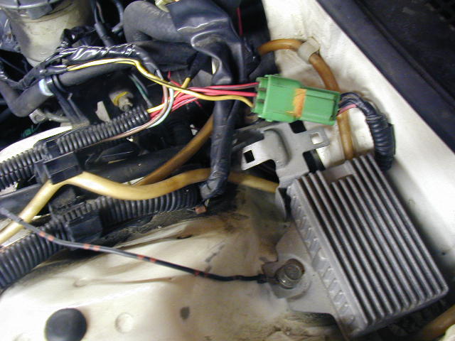
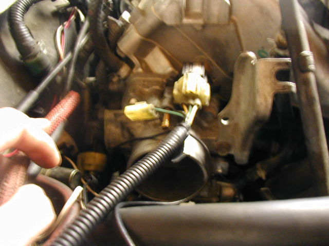
I switched the pins over from the DX distributor connector to the spare SI distributor connector that I had. All 5 wires swapped over, except I had a little confusion afterwards with the 2 white wires (one slim, other fat). I have heard that if the motor won't start to just switch them and that may be the problem. So, after all 5 wires were switched, I added 2 wires, one I labelled "Blue/Green" and the other "Blue/Yellow". I ran those wires into the car to the ecu. |
 |
The next thing I did was switch the 2, out wires with each other on the TPS. I then extended the wires, as noted in order to accomodate for the MPFI TPS location. (It is a tight squeeze on that GSR Intake Manifold and the firewall) |
 |
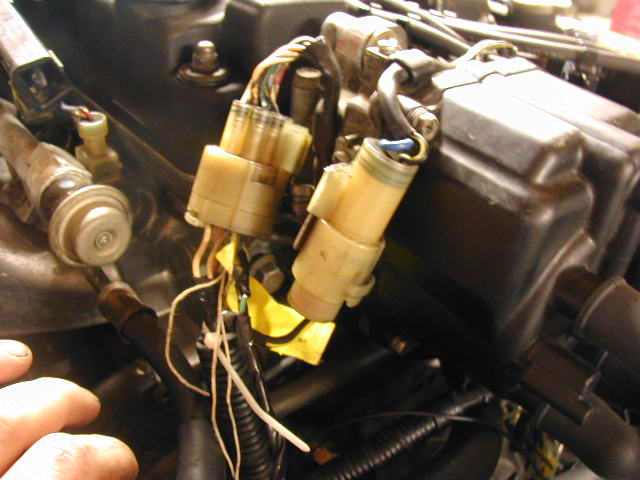
Next was the Injecotr Resistor box. Since, I had a complete SI harness, I just took the whole fuel injector assembly and whatever wires ran off of it to the injector resistor box, intact. As you can see all 4 of the red injector ground wires are connected to the green plug. I then connected the yellow/black stripe wire with the the yellow/black stripe wires of the primary and secondary injectors from the DPFI (which I spliced together). As you can see in the pic, the Brown and Baby blue wires from injectors 1 and 3 respectively have been run to the secondary and primary fuel injectors of the DPFI respectively. The red wire (Inj. 2) and yellow wire (Inj. 4) were run through the firewall to the ecu. (Note:The wire that is grounded to the injector resistor box in the pic is the negative ground wire from the IAB sensor) |
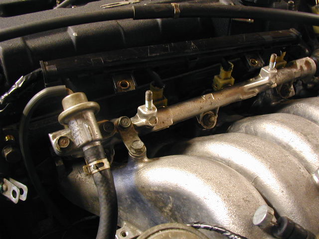 |
Here is a pic of the fuel injectors mounted on the fuel rail/intake manifold of the B18C1 motor. It is hard to notice, but I have all of the wires from the injectors running out towards the driver's side of the car, and no wires running out to the passenger side of the car. I don't know if that makes any difference. |
 |
And now the ecu. At first I read the directions wrong and modified the harness as if it were being plugged into my face, but I realize now that the harness must be viewed as if the wires are coming out towards me. So, here is what I tried. (I have to backtrack my steps and switch the wiring). Pin C1 was moved to B10. Pin C2 was moved to B12. Now, the Blue/Green wire and Blue/Yellow wire (ran in from engine bay) are now connected to pins C1 and C2 respectively. Pins A3 and A7 aren't used any more, so I removed them and ran fuel injector wires, red to A3, and yellow to A7. |
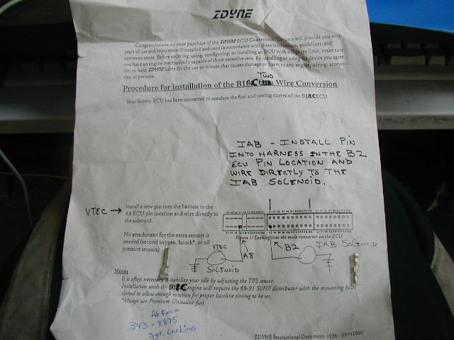 |
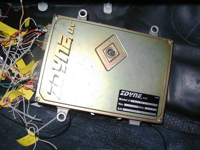
Here are the directions for the Zdyne GSR conversion ecu. I ran the Vtec Solenoid wire to pin A8. And for the IAB, I ran it to pin B2. |
 |
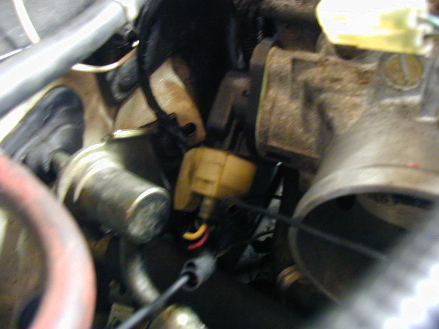
Just for reference, here is the MAP sensor that I am using. I unplugged it from the CRX one on the firewall and plugged it into the GSR one, on the throttle body. This is the big plug. What about that little plug sticking off of the side? Where does that go? |
Thanks for any help you can give me, I just want to get this motor up and running.